300/500V Mica+SR Insulated & Overall Screened Control Cables (2-4 Cores& Multicores)
FFX200E 05mSOZ1-U (PH120)(CU/MGT+SR/OSCR/LSZH 300/500V Class 1)
FFX200E 05mSOZ1-R (PH120)(CU/MGT+SR/OSCR/LSZH 300/500V Class 2
APPLICATION
The cables are primarly intended for use in the following applications:
BS 5266-1 for emergency lighting of premises
BS 5839-1 for fire detection and fire alarm systems in and around building
BS 5839-8 for voice alarm systems
BS 5839-9 for emergency voice communication systems.
 |
 |
STANDARDS
- Basic design to BS 7629-1
FIRE PERFORMANCE
| Circuit Integrity | IEC 60331-21; BS 6387 CWZ; DIN VDE 0472-814(FE180);BS 8434-2 (120mins); BS 5839-1 Clause 26 2e; CEI 20-36/2-1; SS229-1; NBN C 30-004 (cat. F3); NF C32-070-2.3(CR1) |
| Circuit Integrity with mechanical shock | EN 50200(PH120); CEI 20-36/4-0 |
| Circuit Integrity with mechanical shock & water spray | EN 50200 annex E |
| System circuit integrity | DIN 4102-12, E30 depending on lay system |
| Flame Retardance (Single Vertical Wire Test) | EN 60332-1-2; IEC 60332-1-2; BS EN 60332-1-2; VDE 0482-332-1 ; NBN C 30-004 (cat. F1); NF C32-070-2.1(C2); CEI 20-35/1-2; EN 50265-2-1*; DIN VDE 0482-265-2-1* |
| Reduced Fire Propagation(Vertically-mounted bundled wires & cable test) | EN 60332-3-24 (cat. C); IEC 60332-3-24; BS EN 60332-3-24; VDE 0482-332-3; NBN C 30-004 (cat. F2); NF C32-070-2.2(C1); CEI 20-22/3-4; EN 50266-2-4*; DIN VDE 0482-266-2-4 |
| Halogen Free | IEC 60754-1; EN 50267-2-1; DIN VDE 0482-267-2-1; CEI 20-37/2-1 ; BS 6425-1* |
| No Corrosive Gas Emission | IEC 60754-2; EN 50267-2-2; DIN VDE 0482-267-2-2; CEI 20-37/2-2 ; BS 6425-2* |
| Minimum Smoke Emission | IEC 61034-1&2; EN 61034 -1&2; DIN VDE 0482-1034-1&2; CEI 20-37/3-1&2; EN 50268-1&2*; BS 7622-1&2* |
| No Toxic gases | NES 02-713; NF C 20-454 |
Note: Asterisk * denotes superseded standard.
VOLTAGE RATING
- 300/500 V
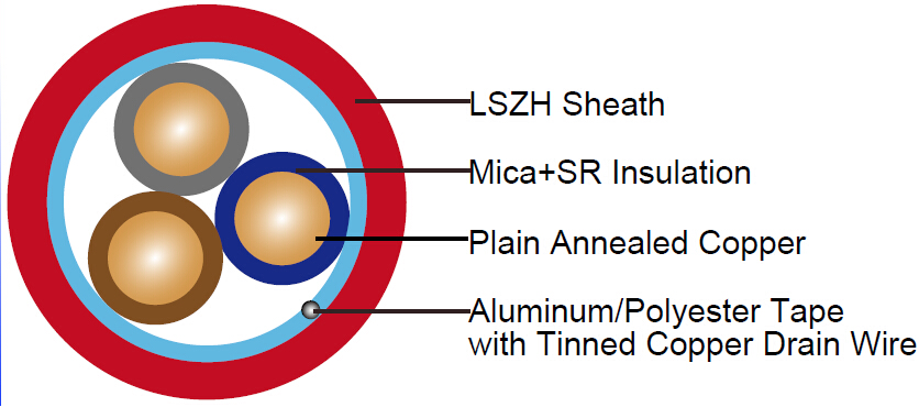
CABLE CONSTRUCTION
| Conductors | Plain annealed copper wire, solid according to IEC 60228 class 1, stranded according to IEC 60228 class 2. |
| Insulation | Mica glass fire resistant tape covered by fire resistant special ceramized silicone rubber compound type EI2 as per BS 7655-1.1 |
| Cabling | The cores are cabled together in concentric layers with suitable non-hygroscopic fillers |
| Overall screen | Aluminum/polyester tape with tinned copper drain wire |
| Circuit Protective Conductor | Uninsulated tinned copper conductor of the same section and class as the insulated conductors in the 2-, 3- and 4-core cables. Drain wire of 0.5mm2 tinned copper conductor is provided in cables of more than 4 conductors |
| Sheath | Thermoplastic LSZH compound type LTS3 as per BS 7655-6.1 (Thermosetting LSZH compound type SW2-SW4 as per BS 7655-2.6 can be offered.). UV resistance, hydrocarbon resistance, oil resistance, anti rodent and anti termite properties can be offered as option |
COLOUR CODE
Insulation Colour as per BS 7629
| Number of cores | Core colours or numbering |
| 2 cores+uninsulated circuit protective conductor | Brown, Blue or Brown, Brown |
| 3 cores+uninsulated circuit protective conductor | Brown, Black, Grey |
| 4 cores+uninsulated circuit protective conductor | Brown, Blue, Black, Grey |
| 7, 12 and19 cores+uninsulated drain wire | Numbers 1, 2, 3, 4, 5, 6, 7 and upwardsor, for identification by colour, an identicalcolour(excluding brown and black),except for twoadjacent cores in each layer distinctively colouredbrown and black. |
Sheath Colour: Orange (other colours upon request)
PHYSICAL AND THERMAL PROPERTIES
| Temperature range during operation (fixed state) | -30°C – +90°C |
| Temperature range during installation (mobile state) | -20°C – +50°C |
| Minimum bending radius | 7.5 x Overall Diameter |
ELECTRICAL PROPERTIES
| Dielectric test | 2000 V r.m.s. x 5' (core/core) |
| Insulation resistance | ≥300 MΩ x km (at 20°C) |
| Short circuit temperature | 350°C |
CONSTRUCTION PARAMETERS
| Cable Code | No. of Core X Cross Section | Nominal Insulation Thickness | Nominal Sheath Thickness | Nominal Overall Diameter | Approx.Weight |
|---|---|---|---|---|---|
| mm2 | mm | mm | mm | kg/km | |
| 2 Cores | |||||
| FFX200E 05mSOZ1-U(PH120) 2G1.0 | 2x1.0 | 0.6 | 0.9 | 7.9 | 85 |
| FFX200E 05mSOZ1-U(PH120) 2G1.5 | 2x1.5 | 0.7 | 0.9 | 8.8 | 105 |
| FFX200E 05mSOZ1-U(PH120) 2G2.5 | 2x2.5 | 0.8 | 1.0 | 10.2 | 150 |
| FFX200E 05mSOZ1-R(PH120) 2G1.5 | 2x1.5 | 0.7 | 0.9 | 9.2 | 110 |
| FFX200E 05mSOZ1-R(PH120) 2G2.5 | 2x2.5 | 0.8 | 1.0 | 10.3 | 155 |
| FFX200E 05mSOZ1-R(PH120) 2G4.0 | 2x4.0 | 0.8 | 1.1 | 12.2 | 220 |
| 3 Cores | |||||
| FFX200E 05mSOZ1-U(PH120) 3G1.0 | 3x1.0 | 0.6 | 0.9 | 8.4 | 105 |
| FFX200E 05mSOZ1-U(PH120) 3G1.5 | 3x1.5 | 0.7 | 0.9 | 9.3 | 130 |
| FFX200E 05mSOZ1-U(PH120) 3G2.5 | 3x2.5 | 0.8 | 1.0 | 10.8 | 190 |
| FFX200E 05mSOZ1-R(PH120) 3G1.5 | 3x1.5 | 0.7 | 0.9 | 9.4 | 135 |
| FFX200E 05mSOZ1-R(PH120) 3G2.5 | 3x2.5 | 0.8 | 1.0 | 10.9 | 190 |
| FFX200E 05mSOZ1-R(PH120) 3G4.0 | 3x4.0 | 0.8 | 1.1 | 13.0 | 280 |
| 4 Cores | |||||
| FFX200E 05mSOZ1-U(PH120) 4G1.0 | 4x1.0 | 0.6 | 1.0 | 9.3 | 125 |
| FFX200E 05mSOZ1-U(PH120) 4G1.5 | 4x1.5 | 0.7 | 1.0 | 10.3 | 165 |
| FFX200E 05mSOZ1-U(PH120) 4G2.5 | 4x2.5 | 0.8 | 1.1 | 12.0 | 240 |
| FFX200E 05mSOZ1-R(PH120) 4G1.5 | 4x1.5 | 0.7 | 1.0 | 10.5 | 170 |
| FFX200E 05mSOZ1-R(PH120) 4G2.5 | 4x2.5 | 0.8 | 1.1 | 12.1 | 250 |
| FFX200E 05mSOZ1-R(PH120) 4G4.0 | 4x4.0 | 0.8 | 1.2 | 14.4 | 350 |
| 7 Cores | |||||
| FFX200E 05mSOZ1-U(PH120) 7G1.0 | 7x1.0 | 0.6 | 1.0 | 10.5 | 175 |
| FFX200E 05mSOZ1-U(PH120) 7G1.5 | 7x1.5 | 0.7 | 1.1 | 12.1 | 230 |
| FFX200E 05mSOZ1-R(PH120) 7G2.5 | 7x2.5 | 0.8 | 1.2 | 15.0 | 340 |
| 12 Cores | |||||
| FFX200E 05mSOZ1-U(PH120) 12G1.5 | 12x1.5 | 0.7 | 1.2 | 16.0 | 380 |
| FFX200E 05mSOZ1-R(PH120) 12G2.5 | 12x2.5 | 0.8 | 1.4 | 20.0 | 560 |
| 19 Cores | |||||
| FFX200E 05mSOZ1-U(PH120) 19G1.5 | 19x1.5 | 0.7 | 1.3 | 17.5 | 470 |
ELECTRICALl PROPERTIES
| Conductor Operating Temperature | 90°C |
| Ambient Temperature | 30°C |
Current-Carrying Capacities (Amp)
| Conductor cross-sectional area | Reference Method A (enclosed in conduit in thermally insulating wall etc) | Reference Method B (enclosed in conduit on a wall or in trunking etc) | Reference Method C (clipped direct) | Reference Method E (in free air or on aperforated cable tray, horizontal or vertical etc) Touching | ||||
|---|---|---|---|---|---|---|---|---|
| 1 two-core cable*, single-phase a.c. or d.c. | 1 three-or four corecable*, three-phase a.c. | 1 two-core cable*, single-phase a.c. or d.c. | 1 three-or four corecable*, three-phase a.c. | 1 two-core cable*, single-phase a.c. or d.c. | 1 three-or four corecable*, three-phase a.c. | 1 two-core cable*, single-phase a.c. or d.c. | 1 three-or four corecable*, three-phase a.c. | |
| 1 | 2 | 3 | 4 | 5 | 6 | 7 | 8 | 9 |
| mm2 | A | A | A | A | A | A | A | A |
| 1.0 | 14.5 | 13 | 17 | 15 | 19 | 17 | 21 | 18 |
| 1.5 | 18.5 | 16.5 | 22 | 19.5 | 24 | 22 | 26 | 23 |
| 2.5 | 25 | 22 | 30 | 26 | 33 | 30 | 36 | 32 |
| 4 | 33 | 30 | 40 | 35 | 45 | 40 | 49 | 42 |
Voltage Drop (Per Amp Per Meter)
| Conductor cross-sectional area | Two-core cables, d.c. | Two-core cable, single-phase a.c. | Three-or four core cable,three-phase a.c. |
|---|---|---|---|
| 1 | 2 | 3 | 4 |
| mm2 | mV/A/m | mV/A/m | mV/A/m |
1.0 |
46 |
46 |
40 |
1.5 |
31 |
31 |
27 |
2.5 |
19 |
19 |
16 |
4 |
12 |
12 |
10 |